All Categories
-
Integrated Circuits (ICs)
Integrated Circuits (ICs)
- Interface - Sensor, Capacitive Touch(642)
- Specialized ICs(12302)
- Power Management (PMIC) - Special Purpose Regulators(5644)
- Power Management (PMIC) - Voltage Regulators - Linear Regulator Controllers(793)
- Power Management (PMIC) - Voltage Regulators - Linear + Switching(1829)
- Power Management (PMIC) - Voltage Regulators - Linear, Low Drop Out (LDO) Regulators(70981)
- Power Management (PMIC) - Voltage Regulators - DC DC Switching Regulators(39569)
- Power Management (PMIC) - DC DC Switching Controllers(13507)
- Power Management (PMIC) - Voltage Reference(9453)
- Power Management (PMIC) - V/F and F/V Converters(145)
- Power Management (PMIC) - Thermal Management(592)
- Power Management (PMIC) - Supervisors(47946)
- Power Management (PMIC) - RMS to DC Converters(170)
- Power Management (PMIC) - Power Supply Controllers, Monitors(2104)
- Power Management (PMIC) - Power Over Ethernet (PoE) Controllers(1008)
- Power Management (PMIC) - Power Management - Specialized(7722)
- Power Management (PMIC) - Power Distribution Switches, Load Drivers(7706)
- Power Management (PMIC) - PFC (Power Factor Correction)(1222)
- Power Management (PMIC) - OR Controllers, Ideal Diodes(705)
- Power Management (PMIC) - Motor Drivers, Controllers(4712)
- Power Management (PMIC) - Lighting, Ballast Controllers(560)
- Power Management (PMIC) - LED Drivers(7282)
- Power Management (PMIC) - Laser Drivers(573)
- Power Management (PMIC) - Hot Swap Controllers(2816)
- Power Management (PMIC) - Gate Drivers(7083)
- Power Management (PMIC) - Full Half-Bridge (H Bridge) Drivers(1342)
- Power Management (PMIC) - Energy Metering(654)
- Power Management (PMIC) - Display Drivers(1435)
- Power Management (PMIC) - Current Regulation/Management(1481)
- Power Management (PMIC) - Battery Management(5553)
- Power Management (PMIC) - Battery Chargers(3831)
- Power Management (PMIC) - AC DC Converters, Offline Switchers(4905)
- Memory - Controllers(358)
- Memory - Configuration PROMs for FPGAs(639)
- Memory - Batteries(13)
- Memory - Memory(65694)
- Logic - Universal Bus Functions(706)
- Logic - Translators, Level Shifters(2854)
- Logic - Specialty Logic(1870)
- Logic - Signal Switches, Multiplexers, Decoders(9420)
- Logic - Shift Registers(2665)
- Logic - Parity Generators and Checkers(335)
- Logic - Multivibrators(831)
- Logic - Latches(3658)
- Logic - Gates and Inverters - Multi-Function, Configurable(1687)
- Logic - Gates and Inverters(16453)
- Logic - Flip Flops(7780)
- Logic - FIFOs Memory(4240)
- Logic - Counters, Dividers(3456)
- Logic - Comparators(592)
- Logic - Buffers, Drivers, Receivers, Transceivers(17835)
- Linear - Video Processing(2909)
- Linear - Comparators(5084)
- Linear - Analog Multipliers, Dividers(263)
- Linear - Amplifiers - Video Amps and Modules(1905)
- Linear - Amplifiers - Special Purpose(1856)
- Linear - Amplifiers - Instrumentation, OP Amps, Buffer Amps(34236)
- Linear - Amplifiers - Audio(4567)
- Interface - Voice Record and Playback(556)
- Interface - UARTs (Universal Asynchronous Receiver Transmitter)(1237)
- Interface - Telecom(4467)
- Interface - Specialized(4833)
- Interface - Signal Terminators(333)
- Interface - Signal Buffers, Repeaters, Splitters(1449)
- Interface - Serializers, Deserializers(1480)
- Interface - Sensor and Detector Interfaces(1524)
- Interface - Modules(169)
- Interface - Modems - ICs and Modules(407)
- Interface - I/O Expanders(1136)
- Interface - Filters - Active(1226)
- Interface - Encoders, Decoders, Converters(714)
- Interface - Drivers, Receivers, Transceivers(20755)
- Interface - Direct Digital Synthesis (DDS)(117)
- Interface - Controllers(3628)
- Interface - CODECS(1676)
- Interface - Analog Switches, Multiplexers, Demultiplexers(12567)
- Interface - Analog Switches - Special Purpose(2533)
- Embedded - System On Chip (SoC)(4496)
- Embedded - PLDs (Programmable Logic Device)(971)
- Embedded - Microprocessors(10083)
- Embedded - Application Specific Microcontrollers(2275)
- Embedded - Microcontrollers(99285)
- Embedded - Microcontrollers, Microprocessor, FPGA Modules(1527)
- Embedded - FPGAs (Field Programmable Gate Array) with Microcontrollers(81)
- Embedded - FPGAs (Field Programmable Gate Array)(27747)
- Embedded - DSP (Digital Signal Processors)(4081)
- Embedded - CPLDs (Complex Programmable Logic Devices)(5187)
- Data Acquisition - Touch Screen Controllers(1210)
- Data Acquisition - Digital to Analog Converters (DAC)(14419)
- Data Acquisition - Digital Potentiometers(6250)
- Data Acquisition - Analog to Digital Converters (ADC)(17776)
- Data Acquisition - Analog Front End (AFE)(787)
- Data Acquisition - ADCs/DACs - Special Purpose(3043)
- Clock/Timing - Real Time Clocks(2446)
- Clock/Timing - Programmable Timers and Oscillators(23469)
- Clock/Timing - IC Batteries(4)
- Clock/Timing - Delay Lines(1049)
- Clock/Timing - Clock Generators, PLLs, Frequency Synthesizers(32775)
- Clock/Timing - Clock Buffers, Drivers(4568)
- Clock/Timing - Application Specific Clock/Timing(8652)
- Audio Special Purpose(1564)
Relevant Manufacturer


-
Discrete Semiconductor Products
Discrete Semiconductor Products
- Current Regulation - Diodes, Transistors(1090)
- Transistors - Special Purpose(226)
- Transistors - Programmable Unijunction(48)
- Transistors - JFETs(1558)
- Transistors - IGBTs - Single(4799)
- Transistors - IGBTs - Modules(63420)
- Transistors - IGBTs - Arrays(26)
- Transistors - FETs, MOSFETs - Single(48330)
- Transistors - FETs, MOSFETs - RF(4903)
- Transistors - FETs, MOSFETs - Arrays(6641)
- Transistors - Bipolar (BJT) - Single, Pre-Biased(4539)
- Transistors - Bipolar (BJT) - Single(25800)
- Transistors - Bipolar (BJT) - RF(2087)
- Transistors - Bipolar (BJT) - Arrays, Pre-Biased(2115)
- Transistors - Bipolar (BJT) - Arrays(2310)
- Thyristors - TRIACs(4044)
- Thyristors - SCRs - Modules(3967)
- Thyristors - SCRs(5436)
- Thyristors - DIACs, SIDACs(319)
- Power Driver Modules(1627)
- Diodes - Zener - Single(87483)
- Diodes - Zener - Arrays(2619)
- Diodes - Variable Capacitance (Varicaps, Varactors)(1200)
- Diodes - RF Diodes(2753)
- Diodes - Rectifiers - Single(67528)
- Diodes - Rectifiers - Arrays(20581)
- Diodes - Bridge Rectifiers(11700)
Relevant Manufacturer


-
RF and Wireless
RF and Wireless
- Subscriber Identification Module (SIM) Cards(77)
- RF Circulators and Isolators(1742)
- RFID, RF Access, Monitoring ICs(1550)
- RFID Transponders, Tags(747)
- RFID Reader Modules(464)
- RFID Evaluation and Development Kits, Boards(30)
- RFID Antennas(329)
- RFI and EMI - Shielding and Absorbing Materials(6444)
- RFI and EMI - Contacts, Fingerstock and Gaskets(7497)
- RF Transmitters(668)
- RF Transceiver Modules and Modems(6900)
- RF Transceiver ICs(4169)
- RF Switches(9276)
- RF Shields(16401)
- RF Receivers(1998)
- RF Receiver, Transmitter, and Transceiver Finished Units(2763)
- RF Power Dividers/Splitters(1223)
- RF Power Controller ICs(86)
- RF Modulators(710)
- RF Mixers(2800)
- RF Misc ICs and Modules(3276)
- RF Front End (LNA + PA)(419)
- RF Evaluation and Development Kits, Boards(747)
- RF Directional Coupler(2718)
- RF Multiplexers(1464)
- RF Detectors(412)
- RF Demodulators(249)
- RF Antennas(12319)
- RF Amplifiers(19651)
- Balun(1496)
- Attenuators(4852)
Relevant Manufacturer


-
Optoelectronics
Optoelectronics
- Optomechanical(480)
- Lighting Fixtures(125)
- Laser Diodes, Laser Modules - Laser Delivery, Laser Fibers(345)
- HeNe Laser Systems(31)
- HeNe Laser Heads(27)
- Display Backlights(93)
- Xenon Lighting(387)
- Touch Screen Overlays(453)
- Panel Indicators, Pilot Lights(75729)
- Remote Phosphor Light Source(269)
- Reflectors(665)
- Light Pipes(5384)
- Lenses(4951)
- Spacers, Standoffs(2718)
- Lamp Replacements(29718)
- Circuit Board Indicators, Arrays, Light Bars, Bar Graphs(9083)
- LED Thermal Products(667)
- LED Lighting Kits(64)
- LED White Lighting(37580)
- LED Color Lighting(4728)
- LED COBs, Engines, Modules, Strips(28735)
- LED Indication - Discrete(27601)
- Laser Diodes, Modules(1553)
- Incandescent, Neon Lamps(311004)
- Cold Cathode Fluorescent (CCFL) & UV Lamps(164)
- Ballasts, Inverters(7728)
- LED Emitters - Infrared, UV, Visible(3871)
- Fiber Optic Transmitters - Drive Circuitry Integrated(4085)
- Fiber Optic Transmitters - Discrete(350)
- Fiber Optic Transceiver Modules(18758)
- Fiber Optic Switches, Multiplexers, Demultiplexers(1387)
- Fiber Optic Receivers(695)
- Fiber Optic Attenuators(654)
- Electroluminescent(102)
- Display, Monitor - LCD Driver/Controller(98)
- Vacuum Fluorescent (VFD)(249)
- LED Dot Matrix and Cluster(865)
- LED Character and Numeric(5421)
- LCD, OLED, Graphic(4654)
- LCD, OLED Character and Numeric(2202)
- Display Bezels, Lenses(88)
- LED Addressable, Specialty(458)
Relevant Manufacturer


-
Sensors, Transducers
Sensors, Transducers
- Industrial Sensors - Ultrasonic Receivers, Transmitters - Industrial(115)
- Industrial Sensors - Thermostats - Mechanical - Industrial(3103)
- Industrial Sensors - Temperature Sensors - Analog and Digital Output - Industrial(209)
- Industrial Sensors - Proximity Sensors - Industrial(13611)
- Industrial Sensors - Pressure Sensors, Transducers - Industrial(26503)
- Optical Sensors - Photonics - Counters, Detectors, SPCM (Single Photon Counting Module)(751)
- Optical Sensors - Camera Modules(875)
- Industrial Sensors - Position, Proximity, Speed (Modules) - Industrial(554)
- Industrial Sensors - Force Sensors, Load Cells - Industrial(346)
- Industrial Sensors - Flow Sensors - Industrial(151)
- Industrial Sensors - Float, Level Sensors - Industrial(310)
- Industrial Sensors - Encoders - Industrial(4980)
- Industrial Sensors - Color Sensors - Industrial(50)
- Touch Sensors(100)
- Ultrasonic Receivers, Transmitters(2421)
- Temperature Sensors - Thermostats - Solid State(1096)
- Temperature Sensors - Thermostats - Mechanical(3397)
- Temperature Sensors - Thermocouples, Temperature Probes(1921)
- Temperature Sensors - RTD (Resistance Temperature Detector)(1525)
- Temperature Sensors - PTC Thermistors(2273)
- Temperature Sensors - NTC Thermistors(13259)
- Temperature Sensors - Analog and Digital Output(3928)
- Strain Gauges(1399)
- Specialized Sensors(1861)
- Solar Cells(503)
- Shock Sensors(84)
- Sensor Interface - Junction Blocks(2519)
- Sensor Cable - Assemblies(22011)
- Proximity/Occupancy Sensors - Finished Units(725)
- Proximity Sensors(2860)
- Pressure Sensors, Transducers(11317)
- Position Sensors - Angle, Linear Position Measuring(6022)
- Optical Sensors - Reflective - Logic Output(194)
- Optical Sensors - Reflective - Analog Output(432)
- Optical Sensors - Phototransistors(1027)
- Optical Sensors - Photointerrupters - Slot Type - Transistor Output(1427)
- Optical Sensors - Photointerrupters - Slot Type - Logic Output(1215)
- Industrial Sensors - Photoelectric, Industrial(16763)
- Optical Sensors - Photodiodes(1543)
- Optical Sensors - Photo Detectors - Remote Receiver(2605)
- Optical Sensors - Photo Detectors - Logic Output(146)
- Optical Sensors - Photo Detectors - CdS Cells(74)
- Optical Sensors - Distance Measuring(377)
- Optical Sensors - Ambient Light, IR, UV Sensors(1305)
- Multifunction(558)
- Motion Sensors - Vibration Sensors(337)
- Motion Sensors - Tilt Switches(67)
- Motion Sensors - Optical Motion Sensors(719)
- Motion Sensors - Inclinometers(175)
- Motion Sensors - IMUs (Inertial Measurement Units)(416)
- Motion Sensors - Gyroscopes(214)
- Motion Sensors - Accelerometers(1911)
- Magnets - Sensor Matched Magnets(119)
- Magnets - Multi Purpose Magnets(1965)
- Magnetic Sensors - Switches (Solid State)(3700)
- Magnetic Sensors - Position, Proximity, Speed (Modules)(5199)
- Magnetic Sensors - Linear, Compass (ICs)(1247)
- Magnetic Sensors - Compass, Magnetic Field (Modules)(35)
- LVDT Transducers (Linear Variable Differential Transformer)(204)
- IrDA Transceiver Modules(196)
- Optical Sensors - Image Sensors, Camera(2235)
- Humidity, Moisture Sensors(1425)
- Gas Sensors(1217)
- Force Sensors, Load Cells(188)
- Flow Sensors(550)
- Float, Level Sensors(1343)
- Encoders(6357)
- Particle, Dust Sensors(43)
- Current Sensors(3455)
- Color Sensors(85)
- Sensor, Transducer Amplifiers(1905)
Relevant Manufacturer


-
Connectors, Interconnects
Connectors, Interconnects
- USB, DVI, HDMI Connectors(446)
- Solid State Lighting Connectors(555)
- Sockets for ICs, Transistors(953)
- Pluggable Connectors(1221)
- Photovoltaic (Solar Panel) Connectors(136)
- Fiber Optic Connectors(370)
- FFC, FPC (Flat Flexible) Connectors(761)
- D-Sub, D-Shaped Connectors(2887)
- Coaxial Connectors (RF)(2389)
- Circular Connectors(14162)
- Blade Type Power Connectors(273)
- AC Power Connectors - Plugs and Receptacles(2597)
- USB, DVI, HDMI Connectors - USB, DVI, HDMI Connector Adapters(572)
- USB, DVI, HDMI Connectors - USB, DVI, HDMI Connector Assemblies(4298)
- Terminals - Wire to Board Connectors(217)
- Terminals - Wire Splice Connectors(4322)
- Terminals - Wire Pin Connectors(328)
- Terminals - Turret Connectors(1273)
- Terminals - Specialized Connectors(2042)
- Terminals - Spade Connectors(3902)
- Terminals - Solder Lug Connectors(345)
- Terminals - Screw Connectors(745)
- Terminals - Ring Connectors(12596)
- Terminals - Lugs(4747)
- Terminals - Quick Connects, Quick Disconnect Connectors(8514)
- Terminals - PC Pin, Single Post Connectors(3776)
- Terminals - PC Pin Receptacles, Socket Connectors(5883)
- Terminals - Magnetic Wire Connectors(1653)
- Terminals - Knife Connectors(112)
- Terminals - Housings, Boots(2850)
- Terminals - Foil Connectors(108)
- Terminals - Barrel, Bullet Connectors(1107)
- Terminals - Terminal Adapters(137)
- Terminal Strips and Turret Boards(1159)
- Terminal Junction Systems(2533)
- Terminal Blocks - Wire to Board(43615)
- Terminal Blocks - Specialized(3722)
- Terminal Blocks - Power Distribution(847)
- Terminal Blocks - Panel Mount(1359)
- Terminal Blocks - Interface Modules(1819)
- Terminal Blocks - Headers, Plugs and Sockets(119920)
- Terminal Blocks - Din Rail, Channel(9373)
- Terminal Blocks - Terminal Block Contacts(65)
- Terminal Blocks - Barrier Blocks(47517)
- Terminal Blocks - Terminal Block Adapters(1059)
- Solid State Lighting Connectors - Solid State Lighting Connector Contacts(271)
- Solid State Lighting Connectors - Solid State Lighting Connector Assemblies(1344)
- Sockets for ICs, Transistors - Socket Adapters(275)
- Sockets for ICs, Transistors - IC Sockets(22148)
- Shunts, Jumpers(907)
- Rectangular Connectors - Spring Loaded(7721)
- Rectangular Connectors - Rectangular Connector Housings(43023)
- Rectangular Connectors - Headers, Specialty Pin(6129)
- Rectangular Connectors - Headers, Receptacles, Female Sockets(229601)
- Rectangular Connectors - Headers, Male Pins(543338)
- Rectangular Connectors - Free Hanging, Panel Mount(30142)
- Rectangular Connectors - Rectangular Connector Contacts(10681)
- Rectangular Connectors - Board In, Direct Wire to Board(2432)
- Rectangular Connectors - Rectangular Connector Adapters(475)
- Rectangular - Board to Board Connectors - Headers, Receptacles, Female Sockets(9)
- Rectangular - Board to Board Connectors - Headers, Male Pins(2)
- Rectangular Connectors - Board Spacers, Stackers (Board to Board)(238901)
- Rectangular Connectors - Arrays, Edge Type, Mezzanine (Board to Board)(37853)
- AC Power Connectors - Power Entry Modules (PEM)(10310)
- Pluggable Connectors - Pluggable Connector Assemblies(6049)
- Photovoltaic (Solar Panel) Connectors - Photovoltaic (Solar Panel) Connector Contacts(77)
- Photovoltaic (Solar Panel) Connectors - Photovoltaic (Solar Panel) Connector Assemblies(504)
- Modular/Ethernet Connectors - Modular/Ethernet Connector Wiring Blocks(99)
- Modular/Ethernet Connectors - Modular/Ethernet Connector (RJ45, RJ11) Plugs(1674)
- Modular/Ethernet Connectors - Modular/Ethernet Connector Plug Housings(181)
- Modular/Ethernet Connectors - Modular/Ethernet Connector (RJ45) Jacks With Magnetics(10152)
- Modular/Ethernet Connectors - Modular/Ethernet Connector (RJ45, RJ11) Jacks(23416)
- Modular/Ethernet Connectors - Modular/Ethernet Connector Adapters(855)
- Memory Connectors - PC Cards - Adapters(21)
- Memory Connectors - PC Card Sockets(3299)
- Memory Connectors - Inline Module Sockets(3390)
- LGH Connectors(764)
- Keystone Connectors - Keystone Inserts(2758)
- Keystone Connectors - Keystone Faceplates, Frames(1926)
- Heavy Duty Connectors - Heavy Duty Connector Inserts, Modules(4190)
- Heavy Duty Connectors - Heavy Duty Connector Housings, Hoods, Bases(17226)
- Heavy Duty Connectors - Heavy Duty Connector Frames(523)
- Heavy Duty Connectors - Heavy Duty Connector Contacts(1832)
- Heavy Duty Connectors - Heavy Duty Connector Assemblies(671)
- Fiber Optic Connectors - Fiber Optic Connector Housings(919)
- Fiber Optic Connectors - Fiber Optic Connector Adapters(4455)
- Fiber Optic Connectors - Fiber Optic Connector Assemblies(3001)
- FFC, FPC (Flat Flexible) Connectors - FFC, FPC (Flat Flexible) Connector Housings(652)
- FFC, FPC (Flat Flexible) Connectors - FFC, FPC (Flat Flexible) Connector Contacts(202)
- FFC, FPC (Flat Flexible) Connectors - FFC, FPC (Flat Flexible) Connector Assemblies(18691)
- D-Sub, D-Shaped Connectors - D-Sub, D-Shaped Connector Terminators(47)
- D-Sub, D-Shaped Connectors - D-Sub, D-Shaped Connector Housings(12238)
- D-Sub, D-Shaped Connectors - D-Sub, D-Shaped Connector Contacts(2714)
- D-Sub, D-Shaped Connectors - D-Sub, D-Shaped Connector Backshells, Hoods(5995)
- D-Sub, D-Shaped Connectors - D-Sub, D-Shaped Connector Adapters(1304)
- D-Sub, D-Shaped Connectors - D-Sub Connector Assemblies(141346)
- D-Sub, D-Shaped Connectors - Centronics Connectors(8770)
- Contacts - Contacts, Spring Loaded (Pogo Pins), and Pressure(630)
- Contacts - Multi Purpose(6196)
- Contacts - Leadframe(122)
- Coaxial Connectors (RF) - Coaxial Connector (RF) Terminators(1231)
- Coaxial Connectors (RF) - Coaxial Connector (RF) Contacts(480)
- Coaxial Connectors (RF) - Coaxial Connector (RF) Adapters(6386)
- Coaxial Connectors (RF) - Coaxial Connector (RF) Assemblies(25734)
- Circular Connectors - Circular Connector Housings(441226)
- Circular Connectors - Circular Connector Contacts(4737)
- Circular Connectors - Backshells and Cable Clamps(53692)
- Circular Connectors - Circular Connector Adapters(8839)
- Circular Connectors - Circular Connector Assemblies(1196254)
- Card Edge Connectors - Card Edge Connector Housings(469)
- Card Edge Connectors - Edgeboard Connectors(672683)
- Card Edge Connectors - Card Edge Connector Contacts(325)
- Card Edge Connectors - Card Edge Connector Adapters(73)
- Blade Type Power Connectors - Blade Type Power Connector Housings(837)
- Blade Type Power Connectors - Blade Type Power Connector Contacts(393)
- Blade Type Power Connectors - Blade Type Power Connector Assemblies(4163)
- Between Series Adapters(649)
- Barrel Connectors - Power Connectors(935)
- Barrel Connectors - Audio Connectors(2432)
- Barrel Connectors - Barrel Connector Adapters(92)
- Banana and Tip Connectors - Jacks, Plugs(1644)
- Banana and Tip Connectors - Binding Posts(239)
- Banana and Tip Connectors - Banana and Tip Connector Adapters(75)
- Backplane Connectors - Specialized(45586)
- Backplane Connectors - Backplane Connector Housings(6863)
- Backplane Connectors - Hard Metric, Standard(6297)
- Backplane Connectors - DIN 41612(9408)
- Backplane Connectors - Backplane Connector Contacts(3583)
- Backplane Connectors - ARINC Inserts(2357)
- Backplane Connectors - ARINC(3789)
Relevant Manufacturer


-
Resistors
-
Capacitors
Capacitors
- Aluminum Capacitors(16817)
- Trimmers, Variable Capacitors(3151)
- Thin Film Capacitors(3473)
- Tantalum Capacitors(136103)
- Tantalum - Polymer Capacitors(9778)
- Silicon Capacitors(320)
- Niobium Oxide Capacitors(330)
- Mica and PTFE Capacitors(9101)
- Film Capacitors(150406)
- Electric Double Layer Capacitors (EDLC), Supercapacitors(2782)
- Ceramic Capacitors(833829)
- Capacitor Networks, Arrays(2383)
- Aluminum Electrolytic Capacitors(125325)
- Aluminum - Polymer Capacitors(7544)
Relevant Manufacturer


-
Transformers
-
Isolators
Isolators
Relevant Manufacturer


-
Crystals, Oscillators, Resonators
-
Switches
Switches
- Interlock Switches(2893)
- Emergency Stop (E-Stop) Switches(1160)
- Cable Pull Switches(571)
- Toggle Switches(33608)
- Thumbwheel Switches(742)
- Tactile Switches(14263)
- Limit Switches(28077)
- Slide Switches(5166)
- Selector Switches(9720)
- Rotary Switches(13850)
- Rocker Switches(53790)
- Pushbutton Switches - Hall Effect(127)
- Pushbutton Switches(190826)
- Programmable Display Switches(39)
- Navigation Switches, Joystick(1882)
- Magnetic, Reed Switches(1399)
- Keypad Switches(637)
- Keylock Switches(3684)
- DIP Switches(7747)
- Configurable Switch Components - Configurable Switch Lens(1435)
- Configurable Switch Components - Configurable Switch Illumination Sources(1236)
- Configurable Switch Components - Configurable Switch Contact Blocks(1401)
- Configurable Switch Components - Configurable Switch Bodies(16077)
- Disconnect Switch Components(2567)
Relevant Manufacturer


-
Relays
Relays
- Safety Relays(1310)
- Reed Relays(1735)
- High Frequency (RF) Relays(1190)
- Contactors (Solid State)(686)
- Contactors (Electromechanical)(11952)
- Automotive Relays(1881)
- Solid State Relays (SSR)(10652)
- Signal Relays, Up to 2 Amps(9149)
- Relay Sockets(2075)
- Power Relays, Over 2 Amps(31604)
- I/O Relay Modules(712)
- I/O Relay Modules - Input(2)
- I/O Relay Module Racks(247)
Relevant Manufacturer


Select Language
Current Language
English
- English
- Deutsch
- Italia
- Français
- 日本語
- 한국의
- русский
- Svenska
- Nederland
- español
- Português
- polski
- Suomi
- Gaeilge
- Slovenská
- Slovenija
- Čeština
- Melayu
- Magyarország
- Hrvatska
- Dansk
- românesc
- Indonesia
- Ελλάδα
- Български език
- Afrikaans
- IsiXhosa
- isiZulu
- lietuvių
- Maori
- Kongeriket
- Монголулс
- O'zbek
- Tiếng Việt
- हिंदी
- اردو
- Kurdî
- Català
- Bosna
- Euskera
- العربية
- فارسی
- Corsa
- Chicheŵa
- עִבְרִית
- Latviešu
- Hausa
- Беларусь
- አማርኛ
- Republika e Shqipërisë
- Eesti Vabariik
- íslenska
- မြန်မာ
- Македонски
- Lëtzebuergesch
- საქართველო
- Cambodia
- Pilipino
- Azərbaycan
- ພາສາລາວ
- বাংলা ভাষার
- پښتو
- malaɡasʲ
- Кыргыз тили
- Ayiti
- Қазақша
- Samoa
- සිංහල
- ภาษาไทย
- Україна
- Kiswahili
- Cрпски
- Galego
- नेपाली
- Sesotho
- Тоҷикӣ
- Türk dili
- ગુજરાતી
- ಕನ್ನಡkannaḍa
- मराठी
INA226 Current Shunt & Power Monitor IC for Accurate Power Monitoring
Time: June 11th, 2026
Browse: 170
The INA226 is a useful current shunt and power monitor designed to measure these values digitally through an I²C or SMBus interface. This article explains what the INA226 is, how it works, its key specifications, pin functions, practical uses, shunt resistor selection, and how it compares with other current sense ICs.
Catalog
Overview of INA226
The INA226 is a current shunt and power monitor with an I²C- and SMBus-compatible interface. It measures both the shunt voltage across an external resistor and the bus supply voltage, then uses internal calibration and multiplication to provide direct digital readings of current and power.
The device can sense current on common-mode bus voltages from 0 V to 36 V, independent of its own supply voltage. It operates from a 2.7 V to 5.5 V supply and typically draws about 330 µA. It also supports programmable calibration, conversion times, averaging, and up to 16 programmable I²C addresses.
If you are interested in purchasing the INA226, feel free to contact us for pricing and availability.
INA226 Key Features and Specifications
|
Parameter |
Specification |
|
Device Type |
Current,
Voltage, and Power Monitor |
|
Bus Voltage
Measurement Range |
0 V to 36 V |
|
Current Sensing
Method |
High-Side and
Low-Side Sensing |
|
Measured
Parameters |
Current,
Voltage, Power |
|
Shunt Voltage
Measurement Range |
±81.92 mV |
|
ADC Resolution |
16-bit |
|
Gain Error
(Maximum) |
±0.1% |
|
Input Offset
Voltage (Maximum) |
10 μV |
|
Averaging Modes |
Configurable |
|
Conversion Time |
Programmable |
|
Communication
Interface |
I²C / SMBus
Compatible |
|
I²C Addresses |
16 Programmable
Addresses |
|
Supply Voltage
(Operating) |
2.7 V to 5.5 V |
|
Power
Calculation |
Internal |
|
Calibration
Register |
User
Programmable |
|
Alert Function |
Programmable
Alert Pin |
|
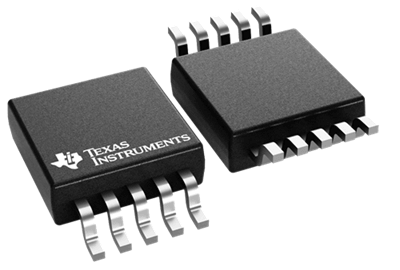
Package Type |
10-Pin VSSOP
(DGS) |
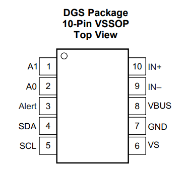
INA226 Pin Configuration and Functions
|
Pin
Number |
Pin
Name |
Type |
Function |
|
1 |
A1 |
Input |
I²C address
selection pin. Used together with A0 to configure one of 16 possible I²C
addresses, allowing multiple INA226 devices on the same bus. |
|
2 |
A0 |
Input |
I²C address
selection pin. Determines the device address along with the A1 pin. |
|
3 |
ALERT |
Output |
Open-drain alert
output. Can generate alerts for overcurrent, undervoltage, overvoltage, power
limits, or conversion-ready events. |
|
4 |
SDA |
Bidirectional
I/O |
Serial Data line
of the I²C interface. Used to transfer configuration commands and measurement
data between the INA226 and the host controller. |
|
5 |
SCL |
Input |
Serial Clock
line of the I²C interface. Provides timing synchronization for data
communication. |
|
6 |
VS |
Power Input |
Device supply
voltage input. Supports an operating voltage range of 2.7 V to 5.5 V. |
|
7 |
GND |
Ground |
Ground reference
for the device and power supply. All voltage measurements are referenced to
this pin. |
|
8 |
VBUS |
Analog Input |
Bus voltage
measurement input. Monitors the voltage of the power rail being measured. |
|
9 |
IN− |
Analog Input |
Negative shunt
voltage input. Connected to one side of the external current-sense resistor. |
|
10 |
IN+ |
Analog Input |
Positive shunt
voltage input. Connected to the other side of the external current-sense
resistor. The voltage difference between IN+ and IN− is used to calculate
current. |
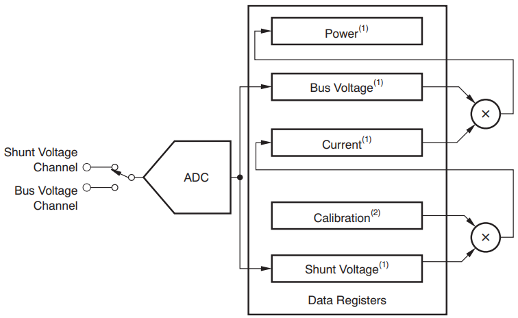
INA226 Internal Block Diagram
This block diagram explains how the INA226 converts analog measurements into useful digital data. The device continuously switches between the shunt voltage channel and the bus voltage channel, sending both signals to its internal analog-to-digital converter (ADC). The ADC converts these analog voltages into digital values that can be processed by the internal registers.
The shunt voltage measurement is combined with the calibration value programmed by the user to calculate the actual load current. The resulting current value is stored in the Current Register, while the measured supply voltage is stored in the Bus Voltage Register. The INA226 then multiplies the current and bus voltage values internally to determine power consumption, which is stored in the Power Register. These calculated values can be accessed through the I²C interface, allowing a microcontroller to monitor current, voltage, and power without performing complex calculations externally.
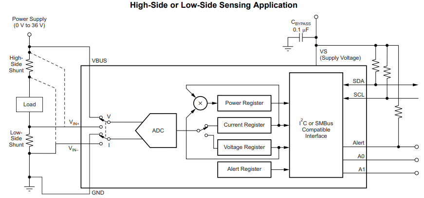
INA226 Application Circuit
The different locations where a shunt resistor can be installed when measuring current with the INA226 is shown in the application circuit below. In a high-side sensing configuration, the shunt resistor is placed between the power supply and the load. This arrangement allows the device to monitor load current while preserving a direct ground connection for the load. High-side sensing is commonly used in battery-powered systems, power supplies, and industrial equipment because it can detect load faults without affecting the ground reference.
In a low-side sensing configuration, the shunt resistor is installed between the load and ground. This method is often simpler to implement because the sensed voltage remains close to ground potential. However, the load no longer shares the same ground reference as the power source, which may not be acceptable in some systems. The INA226 supports both approaches, giving designers flexibility when selecting the most suitable current measurement method for a particular application.
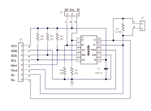
INA226 Typical Connection Circuit
A practical implementation of the INA226 in a real monitoring system. A 0.1 Ω shunt resistor is connected in series with the load so that the INA226 can measure the voltage drop created by load current. The IN+ and IN− pins are connected across the resistor, allowing the device to determine current flow through the load.
The circuit also includes the connections required for communication and operation. The SDA and SCL lines provide I²C communication with a microcontroller, while pull-up resistors ensure reliable signal levels on the bus. A decoupling capacitor is connected between the supply and ground pins to reduce noise and stabilize operation. The A0 and A1 pins allow the I²C address to be configured when multiple INA226 devices share the same communication bus. An ALERT output is also provided, enabling the device to notify the controller when a programmed voltage, current, or power threshold has been exceeded. This diagram serves as a practical wiring example that can be directly adapted for current and power monitoring applications.
Real-World Applications of the INA226
Battery Management Systems
The INA226 is commonly used in battery-powered systems to monitor charging and discharging current. By measuring battery voltage, current flow, and power consumption, it helps improve battery performance and provides accurate information about energy usage. You can also use the data to detect overcurrent conditions and optimize battery life.
Power Supply Monitoring
Many power supplies use the INA226 to monitor output voltage and load current in real time. The device helps engineers verify that the power supply is operating within its design limits and can identify excessive current draw that may indicate a fault or overload condition.
Solar Energy Systems
In solar-powered equipment, the INA226 can track the voltage and current produced by solar panels as well as the power delivered to batteries or loads. This information helps evaluate system efficiency and monitor energy generation under different environmental conditions.
Server and Data Center Equipment
Servers and networking hardware often require precise power monitoring to improve energy efficiency. The INA226 allows system controllers to measure the power consumption of processors, memory modules, storage devices, and power rails, helping operators manage energy usage more effectively.
Industrial Control Systems
Industrial equipment frequently contains motors, sensors, controllers, and communication modules that require reliable power monitoring. The INA226 provides continuous measurements that help detect abnormal operating conditions, reducing the risk of unexpected system failures.
Electric Vehicle Electronics
Electric vehicles contain many electronic subsystems that require current and power monitoring. The INA226 can be used to monitor battery packs, onboard power converters, charging circuits, and auxiliary electronic modules, providing accurate measurement data for system management and protection.
Embedded and IoT Devices
Embedded systems and Internet of Things (IoT) devices often operate under strict power budgets. The INA226 helps developers analyze power consumption during operation, allowing them to optimize firmware, reduce energy usage, and extend battery runtime.
DC Motor and Load Monitoring
The INA226 can monitor the current drawn by DC motors, pumps, fans, and other loads. By tracking changes in current consumption, the system can detect overloads, mechanical faults, stalled motors, or unusual operating conditions before they cause damage.
Choosing the Right Shunt Resistor for INA226
Understanding the Shunt Resistor's Role
A shunt resistor is a very low-value precision resistor connected in series with the load. As current flows through the resistor, a small voltage drop develops across it. The INA226 measures this voltage drop and calculates the current using Ohm's Law.
A larger resistor value produces a larger voltage drop, making current measurements easier and potentially more accurate. However, it also increases power loss and heat generation. A smaller resistor reduces power loss but creates a smaller measurement signal.
Selecting the Resistance Value
The resistor value should be chosen according to the maximum current that the circuit is expected to carry. The goal is to generate a measurable voltage drop while minimizing wasted power.
|
Maximum
Current |
Typical
Shunt Resistor |
|
Below 1 A |
0.1 Ω to 0.5 Ω |
|
1 A to 10 A |
0.01 Ω to 0.1 Ω |
|
10 A to 50 A |
0.001 Ω to 0.01
Ω |
|
Above 50 A |
Less than 0.001
Ω |
For example, a 10 A system commonly uses a 0.01 Ω shunt resistor. At 10 A, the voltage drop is 100 mV, which is well suited for accurate measurement while keeping power loss relatively low.
Calculating Voltage Drop
The voltage drop across the shunt resistor can be calculated using:
VSHUNT=I×RSHUNT
For example, if a load draws 5 A and the shunt resistor is 0.01 Ω:
VSHUNT=5×0.01=0.05V
The INA226 measures this 50 mV drop and uses it to calculate the load current.
Checking Power Dissipation
The resistor must be able to safely handle the power it dissipates. The power loss is calculated using:
P=I2×R
For a 10 A load with a 0.01 Ω shunt resistor:
P=102×0.01=1W
In this case, a resistor rated above 1 W should be selected, typically 2 W or higher, to provide a safety margin and improve reliability.
Importance of Tolerance and Accuracy
For accurate current measurements, a precision resistor with low tolerance should be used. Resistors with ±1%, ±0.5%, or ±0.1% tolerance provide better measurement accuracy than standard resistors. Lower tolerance values reduce measurement errors and improve consistency between devices.
Temperature Coefficient Considerations
As temperature changes, resistor values can drift. A low temperature coefficient (TCR) helps maintain accuracy across different operating temperatures. Precision current-sense resistors typically offer low TCR values that minimize measurement changes caused by heating.
PCB Layout Recommendations
The shunt resistor should be placed close to the INA226 input pins to reduce noise and measurement errors. Short, wide copper traces help minimize additional resistance in the current path. For high-current designs, Kelvin connections are often used to improve sensing accuracy by eliminating errors caused by PCB trace resistance.
INA226 vs Other Current Sense ICs
|
Specification |
INA226 |
INA219 |
INA228 |
ACS712 |
|
Manufacturer |
Texas
Instruments |
Texas
Instruments |
Texas
Instruments |
Allegro
MicroSystems |
|
Current Sensing
Method |
Shunt Resistor |
Shunt Resistor |
Shunt Resistor |
Hall Effect |
|
ADC Resolution |
16-bit |
12-bit |
20-bit |
Analog Output |
|
Bus Voltage
Range |
0 V to 36 V |
0 V to 26 V |
0 V to 85 V |
Not Applicable |
|
Shunt Voltage
Range |
±81.92 mV |
±320 mV |
±163.84 mV |
Internal Hall
Sensor |
|
Shunt Voltage
Resolution |
2.5 µV |
10 µV |
312.5 nV |
Not Applicable |
|
Bus Voltage
Resolution |
1.25 mV |
4 mV |
195.3 µV |
Not Applicable |
|
Gain Error (Max) |
0.1% |
0.5% |
0.05% |
1.5% Typical |
|
Offset Voltage |
10 µV Max |
100 µV Max |
1.6 µV Typical |
Hall Sensor
Offset |
|
Maximum
Common-Mode Voltage |
36 V |
26 V |
85 V |
Isolated Current
Path |
|
Programmable
Addresses |
16 |
4 |
16 |
No |
|
Supply Voltage |
2.7 V to 5.5 V |
3 V to 5.5 V |
2.7 V to 5.5 V |
5 V |
|
Isolation |
No |
No |
No |
Yes (2.4 kVRMS) |
|
Operating
Temperature |
-40°C to +125°C |
-40°C to +85°C |
-40°C to +125°C |
-40°C to +85°C |
|
Typical
Application Level |
Industrial |
General Purpose |
Precision Energy
Monitoring |
High-Current
Isolation |
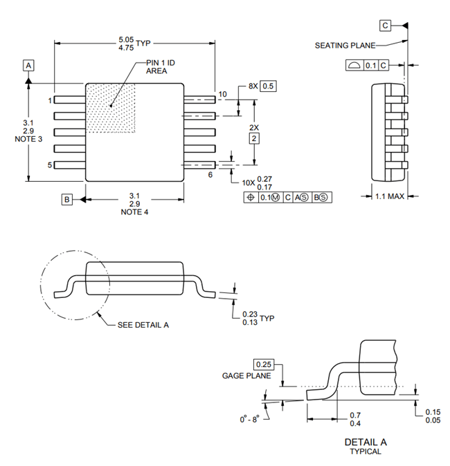
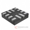
INA226 Mechanical Dimensions
Conclusion
The INA226 is a reliable choice for measuring current, voltage, and power in many electronic systems. Its 16-bit ADC, programmable calibration, I²C/SMBus interface, alert function, and wide bus voltage range make it more useful than a basic current sensor. By converting analog measurements into digital values, it helps reduce the workload of the microcontroller and makes power monitoring easier to implement. To get the best performance from the INA226, the external shunt resistor must be selected carefully. The resistor value, power rating, tolerance, temperature coefficient, and PCB layout all affect measurement accuracy.
Frequently Asked Questions [FAQ]
1. How does the INA226 improve measurement accuracy compared to using an ADC directly on a microcontroller?
The INA226 includes a precision amplifier, a 16-bit ADC, and calibration functions specifically designed for current sensing. This provides higher accuracy and better noise performance than most built-in microcontroller ADCs.
2. Can multiple INA226 devices be connected to the same I²C bus?
Yes. The INA226 supports up to 16 programmable I²C addresses using the A0 and A1 pins, allowing multiple devices to operate on the same communication bus.
3. What happens if the shunt resistor value is entered incorrectly during calibration?
Incorrect calibration settings can cause inaccurate current and power readings. The measured voltage may still be correct, but calculated current and power values will contain errors.
4. Is the INA226 suitable for monitoring very low currents?
Yes. Its 16-bit resolution and low offset voltage allow it to detect small voltage drops across precision shunt resistors, making it suitable for low-current monitoring applications.
5. How does averaging improve INA226 measurement performance?
Averaging combines multiple measurements before reporting a result. This helps reduce noise, improves reading stability, and increases measurement accuracy in electrically noisy environments.
6. Can the INA226 detect abnormal power consumption automatically?
Yes. The ALERT pin can be configured to trigger when current, voltage, or power exceeds user-defined limits, allowing the system to respond quickly to fault conditions.
7. Why is Kelvin sensing recommended when using the INA226?
Kelvin sensing uses separate measurement traces connected directly to the shunt resistor terminals. This reduces errors caused by PCB trace resistance and improves current measurement accuracy.
Related Article
-
![Parallel Plate Capacitor Construction, Working Principle & Formula]() Jun 11 2026Parallel Plate Capacitor Construction, Working Principle & Formula
Jun 11 2026Parallel Plate Capacitor Construction, Working Principle & FormulaA parallel plate capacitor is one of the most important types of capacitors. It is made of two flat conductive plates placed parallel to each other, w... -
![CAN Bus Transceiver Failure Diagnosis and Troubleshooting Steps]() Jun 10 2026CAN Bus Transceiver Failure Diagnosis and Troubleshooting Steps
Jun 10 2026CAN Bus Transceiver Failure Diagnosis and Troubleshooting StepsCAN bus communication is widely used in automotive systems, industrial automation, robotics, medical equipment, and embedded control networks. When a ...

Related products
GRM31A5C2J121JW01D
CAP CER 120PF 630V C0G/NP0 1206

GRM1555C1E7R1DZ01D
CAP CER 7.1PF 25V C0G/NP0 0402
AT25128B-SSHL-T
IC EEPROM 128KBIT SPI 8SOIC

MIC5206-3.3YMM
IC REG LINEAR 3.3V 150MA 8MSOP
PVI5080NPBF
OPTOISO 4KV PHOTOVOLTAIC 8-DIP

TAS5705PAPRG4
TAS5705PAPRG4 TI

SAB-C501G-L24N
SAB-C501G-L24N SIEMENS
LT1209CS
IC OPAMP GP 4 CIRCUIT 16SO

MIP160
panasonic/ TO-220

FDBL86066-F085
MOSFET N-CH 100V 185A 8HPSOF

SPC5601PEMLL6
SPC5601PEMLL6 FREESCALE

PF38F4455LVYTQ1
INTEL BGA
TUSB216RWBR
USB 2.0 REDRIVER